
Skip to content
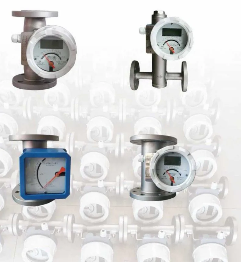
FIG. 01 / 03Metal tube float flowmeters in vertical and horizontal flanged configurations with local indicatorsProduct photograph
Metal tube float flowmeters in vertical and horizontal flanged configurations with local indicators

01 · Flow MetersVariable area

Metal Tube Float (Rotor) Flowmeter

Indiana catalogue ID
II-FM-001
Model line
DN10 – DN200

Variable-area flow measurement for almost any liquid or gas, including low flow and high-temperature media.

Sizes
DN10 – DN200
Water range
1 – 200,000 L/h
Accuracy class
1.5 (1.0 special)

Not sure of the exact model? Request a quote anyway — the team will help select it.

A

Overview

A variable-area flowmeter built from a sensor and an indicator. The sensor carries the flange, measuring tube, cone tube or orifice plate, float and guides; the indicator carries the magnetic coupling system, remote transmission system, display panel, pointer and housing. Small in size with a wide measuring range, it suits low flow rates and high temperature or high pressure media.

Operating principle

  1. 01As fluid flows through the measuring tube the thrust on the float rises. When the float’s own weight balances the buoyancy and thrust of the fluid, the float hovers at a position in the tube.
  2. 02Greater flow means greater thrust, so the float moves further and the gap between the float and the cone tube or orifice plate widens, allowing more flow to pass — which is what makes this a variable-area flowmeter.
  3. 03A magnet embedded in the float couples to the magnetic system in the indicator, so float movement drives the pointer. A magnetic sensor detects the displacement and converts it to an electrical signal; the circuit board then displays instantaneous and cumulative flow.

Product features

  • Remote-transmission type with upper and lower limit alarms that can be set and changed freely
  • LCD shows instantaneous flow, cumulative flow and a percentage bar at the same time, with an always-on backlight
  • Supports standard HART protocol software and hand-held communicators
  • Data storage, backup and recovery, with restore to factory state at any time
  • Multiple installation forms and connection modes for different working conditions

In context

Specified forreal process duty.

  • 01Low flow rate and small flow measurement
  • 02High temperature and high pressure media
  • 03Liquid and gas flow across process lines
  • 04Hygienic service with tri-clamp or SMS connections

B

Technical specifications

Transcribed from the product documentation. A value that is not shown is not stated in the source, and is confirmed with the quotation.

Range and sizing

Range and sizing
Standard diametersDN15, DN25, DN50, DN80, DN100, DN150
Non-standard diametersDN10, DN20, DN32, DN40, DN65, DN125, DN200
Measurement range — water1 to 200,000 L/h
Measurement range — air0.03 to 3,000 m³/h at 20 °C, 0.1013 MPa
Turndown ratio10:1; 20:1 for the special type
Accuracy class1.5; 1.0 for the special type

Process conditions

Process conditions
Pressure rating — flange, DN10 to DN50≤4.0 MPa, maximum 32 MPa
Pressure rating — flange, DN65 to DN150≤1.6 MPa, maximum 16 MPa
Pressure rating — flange, DN200≤1.0 MPa, maximum 10 MPa
Pressure rating — hub connection≤4.0 MPa
Medium temperature — normal type−20 °C to 100 °C
Medium temperature — high temperature type100 °C to 450 °C
Medium temperature — PTFE type0 °C to 80 °C
Ambient temperature — local type−30 °C to 120 °C
Ambient temperature — remote type−20 °C to 80 °C
Medium viscosity — DN15η < 5 mPa·s
Medium viscosity — DN25η < 250 mPa·s
Medium viscosity — DN50 to DN150η < 300 mPa·s

Connection and electrical

Connection and electrical
Flange connection standardsGB/T9112, HG 20592, DIN2501, ANSI, JIS, SH3406
Other connectionsTri-clamp, SMS clamp, threaded, clamp, hose
Power supply12–36 V DC, 4–20 mA two-wire; 220 V AC 50 Hz; battery power supply for continuous use
Output load500 Ω when powered at 24 V
Cable interfaceM20 × 1.5; NPT; G thread
Protection ratingIP65
CommunicationSupports all standard HART protocol software and hand controllers

Materials and construction

Materials and construction
Measuring tube material1Cr18Ni9Ti / 304 · 0Cr18Ni12Mo2Ti / 316 · 316L · PTFE lined · Hastelloy C · Titanium alloy
Additional structureDamping type · clamp-on type · high-temperature modification · high-pressure type · HART communication
Indicator optionsOn-site indicator with no output · smart indicator 4–20 mA square, intrinsically safe Exia II CT3–6 · smart indicator 4–20 mA circular, explosion-proof Exd I CT4–6
Alarm controlUpper limit · lower limit · upper and lower limit
Supply voltage options24 V DC · 220 V AC · 3.6 V lithium battery

Dimensions — vertical, local and intrinsically safe

Dimensions — vertical, local and intrinsically safe
A (mm) by DN15 / 25 / 50 / 80 / 100 / 150 / 200215 / 225 / 250 / 265 / 275 / 365 / 395
B (mm) by DN15 / 25 / 50 / 80 / 100 / 150 / 200150 / 150 / 155 / 210 / 230 / 285 / 345
Weight (kg) by DN15 / 25 / 50 / 80 / 100 / 150 / 2005 / 7 / 10 / 16.5 / 18 / 36 / 51
Standard height250 mm, minimum 200 mm; custom heights on request

Dimensions — vertical, flameproof

Dimensions — vertical, flameproof
A (mm) by DN15 / 25 / 50 / 80 / 100 / 150 / 200155 / 175 / 215 / 265 / 290 / 320 / 400
B (mm) by DN15 / 25 / 50 / 80 / 100 / 150 / 200235 / 245 / 270 / 285 / 295 / 390 / 420
Weight (kg) by DN15 / 25 / 50 / 80 / 100 / 150 / 2005 / 7 / 10 / 16.5 / 18 / 36 / 51
Flow ranges by bore and float
BoreFloat codeWater, stainless steel float (L/h)Water, PTFE or Ti float (L/h)Air (m³/h)
DN15S15.0 – S15.1010 – 1,00025 – 4000.5 – 30
DN25S25.0 – S25.91,000 – 10,000600 – 3,00030 – 300
DN50S50.0 – S50.66,000 – 25,0004,000 – 16,000180 – 750
DN80S80.0 – S80.425,000 – 60,00016,000 – 40,000750 – 1,800
DN100S100.0 – S100.360,000 – 125,00040,000 – 100,0001,800 – 3,000
DN150S150.1 – S150.2130,000 – 160,000100,000 – 130,0004,000
DN200S200.1 – S200.2165,000 – 200,000135,000 – 170,000—
  • Water and air figures are the maximum flow for each float code at 0.1013 MPa absolute and 20 °C. Pressure loss figures in the manual should be checked against the application; low pressure loss requires negotiation with the manufacturer.

Source · INDIANA INSTRUTECH · Metal Tube Float (Rotor) Flowmeter — operating instruction

C

Installation

Guidance from the product’s operating documentation.

  1. 01Vertical installation is the most widely used configuration, usually bottom-inlet to top-outlet. Horizontal spring and horizontal T-type installations are also available.
  2. 02Straight pipe requirement: inlet 5 times the nominal diameter, outlet 250 mm.
  3. 03Where the medium contains ferromagnetic material, fit a magnetic filter at the flowmeter inlet — diameter height 100 mm up to DN100, 150 mm above DN100. For non-ferromagnetic impurities, fit a filter at the inlet.
  4. 04Keep the instrument more than 300 mm away from ferromagnetic metal material and away from strong magnetic fields.
  5. 05Remove the buffer paper pad at the inlet end before installation.
  6. 06Open the valve slowly. Opening it quickly drives the float into the stopper and can damage the instrument.
  7. 07Clean the sensor interior periodically — impurities or ferromagnetic material adsorbed on the float will stick it or spoil accuracy.
  8. 08Keep the relative position of sensor and indicator unchanged; changing it directly affects measurement accuracy.
  9. 09Store at −40 to +55 °C, protected from rain, snow, direct exposure and corrosive media.

D

Applications and industries

Documented in the product literature, not inferred.

Applications

  • Low flow rate and small flow measurement
  • High temperature and high pressure media
  • Liquid and gas flow across process lines
  • Hygienic service with tri-clamp or SMS connections

Industries

  • Petroleum
  • Chemical
  • Steel and metallurgy
  • Pharmaceutical water production
  • Environmental protection

To specify or quote this, the team needs

  • Line size and connection standard
  • Medium — liquid or gas — with density and viscosity
  • Flow range required, minimum and maximum
  • Operating pressure and temperature
  • Structural style — bottom-in top-out, side-in side-out, and so on
  • Measuring tube material
  • Indicator type and hazardous-area requirement
  • Alarm contacts required
  • Supply voltage — 24 V DC, 220 V AC or lithium battery
Request a Quote

Request for quotation · II-FM-001

Request a quotation for the Metal Tube Float (Rotor) Flowmeter

The product, its Indiana catalogue ID are attached to the request automatically. Add quantities and your process conditions — or ask for help selecting the right model.