II-LT-001 · LEVEL
Guided-wave radar
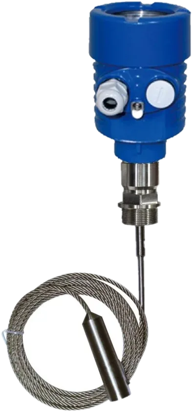
Guided-Wave Radar Level Gauge
70X series
Contact level measurement for liquids and solid powders in complex process conditions.
- Range
- Up to 30 m
- Accuracy
- ±10 mm
- Output
- 4–20 mA / HART
Industrial instrumentation · Est. 2014 · MSME & IEC registered


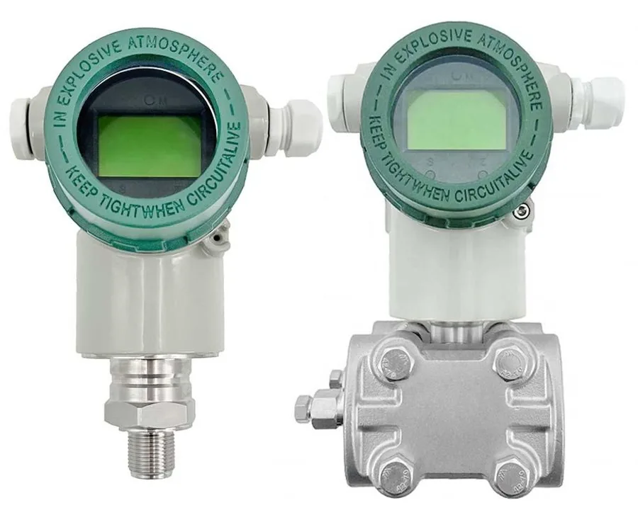
03 · Pressure MetersMonocrystalline silicon
Gauge, vacuum, high-temperature and differential pressure transmitters with LCD and 4–20 mA + HART.
Not sure of the exact model? Request a quote anyway — the team will help select it.
A
A calibrated-range family covering gauge pressure to 200 kg/cm², vacuum to −1 kg/cm², high-temperature service with Hastelloy C-276 diaphragms, and monocrystalline silicon differential pressure from −100 mmWC to 25,000 mmWC. All models are two-wire 4–20 mA with HART and an integral LCD.
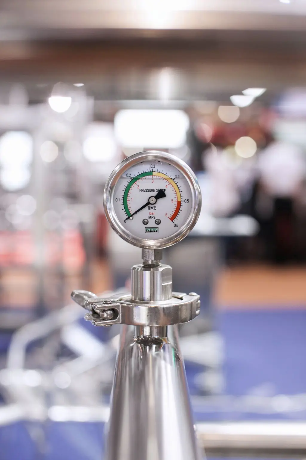
In context
B
10 documented configurations. Open one to see its specification.
| Display | LCD |
|---|---|
| Output | 4–20 mA + HART, two-wire |
| Power supply | 24 V DC |
| Accuracy | 0.2% F.S. |
| Measurement range | 0–200 kg/cm² |
| Maximum working pressure | 500 kg/cm² |
| Process connection | 1/2″ NPT female |
| Calibration | 0–200 kg/cm² corresponds to 4–20 mA output |
| Display | LCD |
|---|---|
| Output | 4–20 mA + HART, two-wire |
| Power supply | 24 V DC |
| Accuracy | 0.2% F.S. |
| Measurement range | −1 to 0 kg/cm² |
| Process connection | 1/2″ NPT female |
| Electrical interfaces | 2 electrical connection ports |
| Display | LCD |
|---|---|
| Output | 4–20 mA + HART, two-wire |
| Power supply | 24 V DC |
| Accuracy | 0.2% F.S. |
| Threaded connection | 1/2″ NPT female |
| Diaphragm material | Hastelloy C-276 |
| Operating temperature | −40 to 85 °C |
| Measurement range | 0 to 5 kg/cm² |
| Maximum working pressure | 25 kg/cm² |
| Display | LCD |
|---|---|
| Output | 4–20 mA + HART, two-wire |
| Power supply | 24 V DC |
| Accuracy | 0.2% F.S. |
| Threaded connection | 1/2″ NPT female |
| Diaphragm material | Hastelloy C-276 |
| Operating temperature | −40 to 85 °C |
| Measurement range | −1 to 3 kg/cm² |
| Maximum working pressure | 6 kg/cm² |
| Display | LCD |
|---|---|
| Output | 4–20 mA + HART, two-wire |
| Power supply | 24 V DC |
| Accuracy | 0.2% F.S. |
| Threaded connection | 1/2″ NPT female |
| Diaphragm material | Hastelloy C-276 |
| Operating temperature | −40 to 85 °C |
| Measurement range | 0 to 10 kg/cm² |
| Maximum working pressure | 16 MPa |
| Display | LCD |
|---|---|
| Output | 4–20 mA + HART, two-wire |
| Power supply | 24 V DC |
| Accuracy | 0.075% F.S. |
| Differential pressure range | −100 to 900 mmWC |
| Static pressure rating | 16 MPa |
| Wetted parts material | SS316 |
| Diaphragm material | Hastelloy C-276 |
| Clamp material | 304 stainless steel |
| Electrical connection | 1/2″ NPT female |
| Mounting bracket | 2-inch pipe mount bracket |
| Display | LCD |
|---|---|
| Output | 4–20 mA + HART, two-wire |
| Power supply | 24 V DC |
| Accuracy | 0.075% F.S. |
| Differential pressure range | 0 to 2,500 mmWC |
| Static pressure rating | 16 MPa |
| Wetted parts material | SS316 |
| Diaphragm material | Hastelloy C-276 |
| Clamp material | 304 stainless steel |
| Electrical connection | 1/2″ NPT female |
| Mounting bracket | 2-inch pipe mount bracket |
| Display | LCD |
|---|---|
| Output | 4–20 mA + HART, two-wire |
| Power supply | 24 V DC |
| Accuracy | 0.075% F.S. |
| Differential pressure range | 0 to 25,000 mmWC |
| Static pressure rating | 25 MPa maximum |
| Wetted parts material | SS316 |
| Diaphragm material | Hastelloy C-276 |
| Clamp material | 304 stainless steel |
| Electrical connection | 1/2″ NPT female |
| Mounting bracket | 2-inch pipe mount bracket |
| Display | LCD |
|---|---|
| Output signal | 4–20 mA + HART |
| Power supply | 24 V DC |
| Accuracy | 0.1% F.S. |
| Measurement range | −40 to +40 kPa |
| Allowable static pressure | At least 3 bar |
| Wetted parts material | 316L stainless steel |
| Bolts and nuts | 316L stainless steel |
| Clamp material | 304 stainless steel |
| Medium | Air |
| Medium temperature | 20–90 °C |
| Mounting orientation | High-pressure side on the left |
| Electrical connection | Dual M20 × 1.5 female threads |
| Ingress protection | IP66 |
| Display | LCD |
|---|---|
| Output signal | 4–20 mA + HART |
| Power supply | 24 V DC |
| Accuracy | ±0.25% F.S. |
| Flange size | 2 inch |
| Flange rating | ASME Class 300# |
| Flange material | SS304 |
| Diaphragm material | SS316L |
| Seal configuration | Remote diaphragm flange seals |
| Capillary length | 2 m |
| Process fluid | NH₃ (liquid ammonia) |
| Process fluid density | 0.65 kg/L (approximately 650 kg/m³) |
| Operating temperature | −11 °C |
| Operating pressure | 1.85 kg/cm² |
| Design temperature | −5 °C |
| Design pressure | 25 kg/cm² |
| Measuring / calibration height | 813 mm |
| Tag number (as supplied) | 12LC232 |
C
Transcribed from the product documentation. A value that is not shown is not stated in the source, and is confirmed with the quotation.
| Output | 4–20 mA with HART, two-wire, as specified for each model |
|---|---|
| Power supply | 24 V DC, as specified for each model |
| Display | LCD showing pressure, current and 0–100% proportional display |
| Communication | HART protocol using BELL202 FSK, 1200 Hz or 2000 Hz superimposed on the 4–20 mA signal |
| A/D conversion | 18-bit |
| Configuration memory | EEPROM, non-volatile |
| Mounting | 2-inch pipe, wall or instrument panel |
|---|---|
| Electronic compartment | Rotates 90° left and right after loosening the locking screw — do not rotate beyond 90° |
| DP process connection holes | 1/4-18 NPT, requiring thread sealing |
| DP connection hole centre distance | 54 mm standard; 50.8 mm, 54 mm or 57.2 mm by rotating the waist flange joint |
| Recommended cable | Explosion-proof cable gland, cable diameter 8–12 mm |
| Signal cable | Shielding not required but stranded wire is preferred; keep away from power cables and strong electrical equipment |
| Insulation testing | Do not use a high-voltage megohm meter — test voltage must not exceed 100 V |
| Output current limit | Intrinsically safe design, output limited to less than 24 mA DC |
| Keys | M — menu · S — set · Z — select / OK |
|---|---|
| Menu 2 | Change the primary variable unit |
| Menu 3 / 4 | Change the lower and upper range limits |
| Menu 5 | Change damping |
| Menu 6 | Zero the primary variable (shortcut: hold M + Z for 5 seconds) |
| Menu 8 | Output characteristic — linear or square root |
| Menu 21 | Liquid level density, in g/cm³, used when the primary variable unit is a height unit |
| Factory reset | Damping time set to 88.888, or value +5678.0 on the mainboard display |
| Menu timeout | Returns to measurement state after approximately 15 seconds with no key operation |
Source · INDIANA INSTRUTECH · Pressure & Differential Pressure Transmitters — technical product catalogue · Monocrystalline silicon pressure / differential pressure — installation and operating manual · IIT-3051DG monocrystalline silicon differential pressure transmitter · IIT-3051DP-SF dual-flange differential pressure transmitter
The supplied datasheets list these models with a ZT- prefix (ZT-2188-H, ZT-2188-G, ZT-3051DRG, ZT-3051DG, ZT-3051DP-SF).
D
Guidance from the product’s operating documentation.
E
Documented in the product literature, not inferred.
F
Branded PDFs generated from this page's own data — nothing in them that isn't on the site.
Request for quotation · II-PT-001
The product, its Indiana catalogue ID are attached to the request automatically. Add quantities and your process conditions — or ask for help selecting the right model.
II-LT-001 · LEVEL
Guided-wave radar
70X series
Contact level measurement for liquids and solid powders in complex process conditions.
II-PT-002 · PRESSURE
Pressure transducer
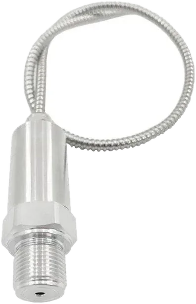
IIT-2166-F
Compact 0–250 bar loop-powered transducer with braided cable, built for hydraulic service.
II-FM-002 · FLOW
Transit-time ultrasonic
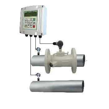
IIT-200F
Transit-time flow and thermal energy measurement from DN15 to DN6000, clamp-on, insertion or inline.