II-LT-002 · LEVEL
76–81 GHz FMCW radar
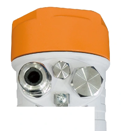
76–81 GHz FMCW Radar Level Transmitter
76–81 GHz
Non-contact level to 120 m with an 8 cm blind spot and a 3° beam.
- Range
- 0.1 – 120 m
- Accuracy
- ±1 mm
- Beam angle
- 3° or 8°
Industrial instrumentation · Est. 2014 · MSME & IEC registered


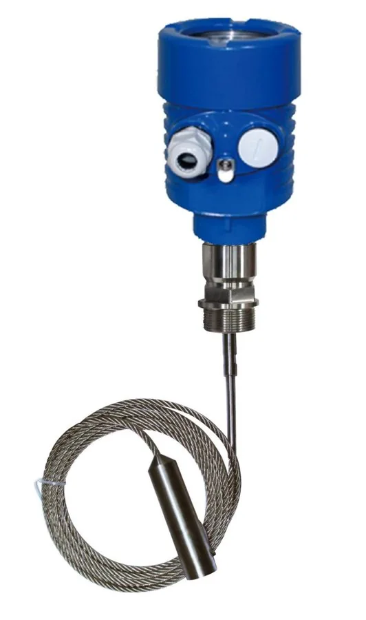
02 · Level TransmittersGuided-wave radar
Contact level measurement for liquids and solid powders in complex process conditions.
Not sure of the exact model? Request a quote anyway — the team will help select it.
A
High-frequency microwave pulses travel along a cable or rod probe. Where the probe meets the measured medium the change in dielectric constant reflects part of the pulse back, and the interval between the transmitted and reflected pulse is proportional to the distance to the surface. Six probe configurations cover liquids, powders, high temperature and pressure, corrosive media and low dielectric constants.
In context
B
6 documented configurations. Open one to see its specification.
| Frequency | 500 MHz – 1.8 GHz |
|---|---|
| Signal output | 4–20 mA / HART |
| On-site display | Four LCD programmable displays |
| Power source | Two-wire (DC 24 V) / four-wire (DC 24 V or AC 220 V) |
| Process connection | Thread / flange (optional) |
| Explosion-proof certification | Exia IIC T6 Ga / Exd ia IIC T6 Gb |
| Applicable medium | Liquids, solid powders |
|---|---|
| Measurement range | 30 m |
| Antenna | Single-cable antenna |
| Process temperature | −40 to 250 °C |
| Process pressure | −0.1 to 4 MPa |
| Measurement accuracy | ±10 mm |
| Applicable medium | Liquid |
|---|---|
| Measurement range | 6 m |
| Antenna | Single-pole antenna |
| Process temperature | −40 to 250 °C |
| Process pressure | −0.1 to 4 MPa |
| Measurement accuracy | ±10 mm |
| Applicable medium | Liquids, solid powders |
|---|---|
| Measurement range | 30 m |
| Antenna | Dual-cable antenna |
| Process temperature | −40 to 200 °C |
| Process pressure | −0.1 to 4 MPa |
| Measurement accuracy | ±10 mm |
| Dielectric constant | Any dielectric material ≥1.6 |
| Applicable medium | Liquids under high temperature and high pressure |
|---|---|
| Measurement range | 6 m |
| Antenna | Single-cable or single-pole antenna |
| Process temperature | −40 to 400 °C |
| Process pressure | −0.1 to 40 MPa |
| Measurement accuracy | ±10 mm |
| Applicable medium | Liquids, particularly highly corrosive liquids |
|---|---|
| Measurement range | 6 m |
| Antenna | Fully tetrafluoroethylene-sealed cable-type or rod-type antenna |
| Process temperature | −40 to 200 °C |
| Process pressure | −0.1 to 4 MPa |
| Measurement accuracy | ±10 mm |
| Applicable medium | Liquids, particularly those with low dielectric constants |
|---|---|
| Measurement range | 6 m |
| Antenna | Coaxial tubular antenna |
| Process temperature | −200 to 250 °C |
| Process pressure | −0.1 to 4 MPa |
| Measurement accuracy | ±10 mm |
C
Transcribed from the product documentation. A value that is not shown is not stated in the source, and is confirmed with the quotation.
| Measurement accuracy | ±10 mm |
|---|---|
| Resolution | 1 mm |
| Measurement interval | Approximately 1 s, depending on parameter settings |
| Adjust time | Approximately 1 s, depending on parameter settings |
| Frequency | 500 MHz – 1.8 GHz |
| Minimum dielectric constant | ≥1.8 for rod probes; ≥1.6 using dual-cable measurement; ≥1.3 inside a guided-wave tube |
| Viscosity | Generally ≤500 cSt |
| Output signal | 4–20 mA / HART |
|---|---|
| Resolution | 1.6 µA |
| Fault signal | Current output remains unchanged; 20.5 mA; 22 mA; 3.9 mA |
| Four-wire load resistor | Maximum 500 Ω |
| Integration time | 0–40 s, adjustable |
| Two-wire, standard type | 16–26 V DC |
|---|---|
| Two-wire, intrinsically safe type | 21.6–26.4 V DC |
| Maximum current consumption (two-wire) | 22.5 mA |
| Four-wire, intrinsically safe + explosion-proof | 22.8–26.4 V DC, 198–242 V AC |
| Maximum power consumption (four-wire) | 1 VA, 1 W |
| Permitted ripple | <100 Hz: Uss < 1 V · 100 Hz–100 kHz: Uss < 10 mV |
| Rod probe | Stainless steel 316L / PTFE |
|---|---|
| Cable probe | Stainless steel 316L / PTFE |
| Coaxial probe | Stainless steel 316L / PTFE |
| Sealant | Viton fluororubber, Kalrez fluororubber |
| Process connection | Stainless steel 316L |
| Shell | Aluminium, plastic or stainless steel 316L; cast aluminium with powder layer |
| Shell window | Polycarbonate |
| Ground terminal | Stainless steel 316L |
| Working, storage and transport temperature | −40 to 80 °C |
|---|---|
| Relative humidity | <95% |
| Maximum pressure inside tank | 40 MPa |
| Seismic resistance | Mechanical vibration 10 m/s², 10–150 Hz |
| Protection rating | IP66 / IP67 |
| Cable inlet | One M20 × 1.5 cable inlet for cables 5–9 mm diameter, plus one M20 × 1.5 blind plug |
|---|---|
| Terminal | Spring terminal for wires up to 2.5 mm² cross-section |
| Cable type | Standard two-core cable, outer diameter 5–9 mm; shielded cable recommended where electromagnetic interference is present |
| Shielding | Both ends of the shielded cable must be grounded; the external grounding terminal on the housing must be connected to earth |
| Rating | Exia IIC T6 — intrinsically safe, die-cast aluminium housing with adhesive-sealed electronics |
|---|---|
| Associated safety barrier | FBS-2 safety barrier, [Exia] IIC, operating voltage 21.6–26.4 V DC, short-circuit current 135 mA, operating current 4–20 mA |
| Maximum cable length to barrier | 500 m, shielded cable |
| Distributed capacitance / inductance | ≤0.1 µF/km · ≤1 mH/km |
| Model code | Maximum measuring distance (cable / rod) | Process temperature at antenna section |
|---|---|---|
| 311 | 30 m / 6 m | −40 to 250 °C |
| 312 | 20 m / 6 m | −40 to 200 °C |
| 313 | 30 m / 6 m | −40 to 150 °C |
| 314 | 6 m | −40 to 250 °C |
| 315 | 15 m / 6 m | −200 to 400 °C |
Source · INDIANA INSTRUTECH · Guided-Wave Radar Level Gauge — operating instruction
D
Guidance from the product’s operating documentation.
E
Documented in the product literature, not inferred.
F
Branded PDFs generated from this page's own data — nothing in them that isn't on the site.
Request for quotation · II-LT-001
The product, its Indiana catalogue ID are attached to the request automatically. Add quantities and your process conditions — or ask for help selecting the right model.
II-LT-002 · LEVEL
76–81 GHz FMCW radar
76–81 GHz
Non-contact level to 120 m with an 8 cm blind spot and a 3° beam.
II-LT-003 · LEVEL
Ultrasonic, non-contact
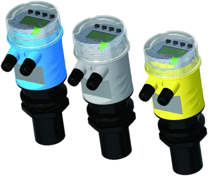
5 m – 25 m
Non-contact level with built-in LCD, 4–20 mA output and two-relay pump control on the four-wire model.
II-PT-001 · PRESSURE
Monocrystalline silicon
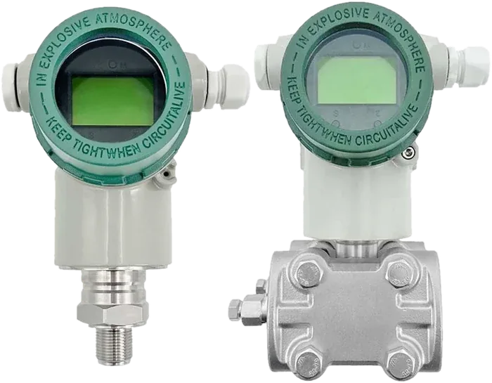
IIT-2188-H · IIT-2188-G · IIT-3051DRG · IIT-3051DG · IIT-3051DP-SF
Gauge, vacuum, high-temperature and differential pressure transmitters with LCD and 4–20 mA + HART.